About Us
Homeowners/Remodelers
Commercial/Institutional
Architects/Designers
Photo Gallery

ENERJOY I Specifications

Bid Specifications:
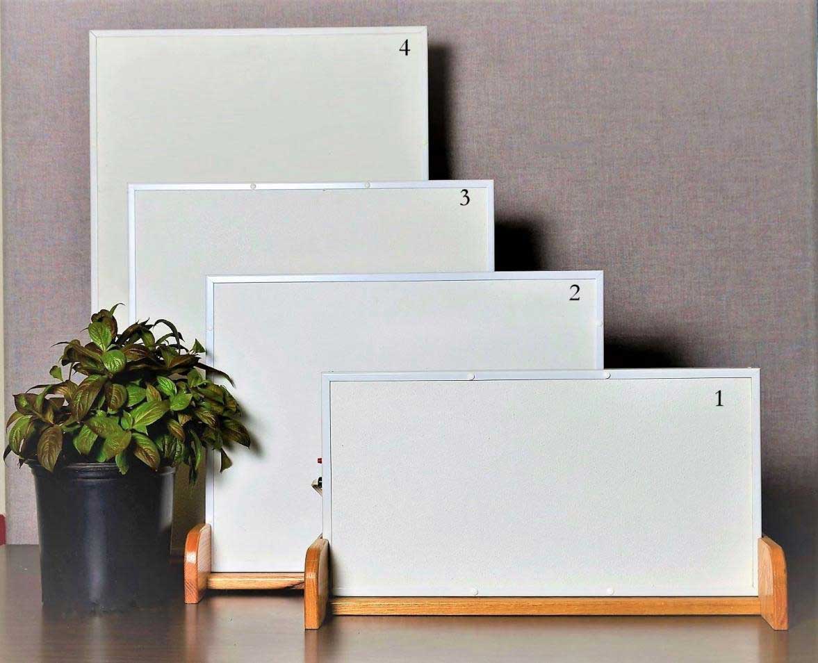
The ENERJOY® radiant heating panel shall be constructed of insulated Solid State Heating element. The element shall be backed with one-inch thick, high density, odorless fiberglass board, faced with a white finely textured aluminum face and framed in aluminum. Panels shall reach the full surface temperature in five minutes. Radiant output shall be 95% of input energy. Panels shall be listed under UL Standard 2021 – Fixed and Location-Dedicated Electric Room Heaters. Panel shall meet or exceed FHA/HUD Minimum Property Standards.

Contents:

ENERJOY Pictures

enerjoy I Panel


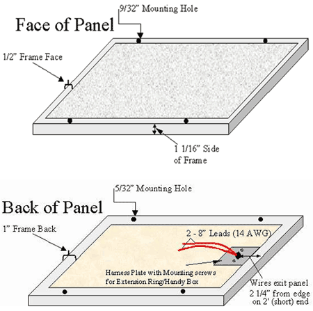
Dimensions


Installation - (For a PDF Click Here)

INSTALLATION of the multi-sized panels is as easy as an electric light fixture – mounted on the surface, flush, placed in a suspended ceiling grid, or freely suspended. Painting, overspraying with water base acoustical material, or framing creates the desired aesthetic effect. Do no operate until dry.
Penetrable Surface Mounting (sheetrock) (Fig. 1)-(check for bag of hole plugs)

  1. Insure adequate clearance hole in center for module connection box.
  2. Install connection box to back of module using the prepositioned screws.
  3. Connect the power supply conductors to the module leads in the connection box.
  4. Position on ceiling, holding module in place.
  5. Punch or drill holes into the ceiling to provide a hole for the screw/anchor assembly, or mark holes for drill.  The frame mounting holes are designed to accept #6 -1 ¾” Pan head screws.
  6. Insert installer provided screw/anchor assembly into the ceiling, and tighten into place. Insert plastic caps to close frame screw holes.

T-Bar Mounting (Fig. 2)

  1. Install connection box to back of module using the two prepositioned screws.
  2. Lay the module carefully onto the T-Bar grid and secure with installer provided hold-down clips if necessary.
  3. Connect the power supply conductors to the module leads in the module connection box.

UL Logo for US and Canada

This is a description of a major benefit of using the product.
Inpenetrable Surface Mounting - RPD model (Concrete) (Fig. 3)

  • Assemble Wiremold junction box and rear plate and attach to the side of the panel frame with the provided hardware.
  • Position panel and junction box assembly onto ceiling to mark the location of the panel and junction box mounting holes.
  • Drill holes (3-1/16" dia., 1-1/4" deep) at each mark and insert anchors into drilled holes.
  • Hold the panel and junction box assembly to the ceiling; insert screw completely through large frame hole and screw securely through small frame hole into anchor.
  • Bring Wiremold raceway through appropriate knockout of panel junction box.
  • Connect the power supply conductors to the panel leads: Attach the grounding conductor to the provided ground clip.

Heatmodule Operations Test

Each panel has been individually checked at the factory. However each panel should be field checked by measuring cold resistance for confirmation with label wattage. After panel installation, the entire circuit should be tested, to check the on-sight electrical work. Two methods of testing will be discussed in the following paragraphs.
Full Power Available - Apply rated voltage to the heater load circuit. Branch loads are to be read with a suitable amp meter. The amp meter value should be the same as that calculated for the heating load and, if the values agree, all panels are operating. If the values do not agree, installation should be re-checked. For physical check without a meter, it is only necessary to feel the panels. If they are warm but can only be touched for a few seconds, they are working.
Without Power Available - This check of the panel installation requires the use and knowledge of an ohmmeter. A resistance measurement is taken at the load circuit, with all other circuits isolated. This will give the total resistance of the heater load. Knowing the total heater load of the panel in watts and the heater rated voltage, a simple calculation will give the same values as that read on the ohm meter. (The same test procedure applies of an individual panel)  Example: For a branch circuit of 1500 watts and panel rated voltage of 240, the resistance will be 38.4 ohms:

ENERJOY I Specifications - (for a PDF Click Here)

All sizes also available in 208 and 277 volt     (other sizes and wattages available)

Model No.

Voltage

Watts

BTUH

Amperage

Size

Weight(lbs.)

Under Desk Heaters

12UDH-4

120

100

341

0.8

11¾" x 23¾" x 1 1/8"

3

22UDH-4

120

200

683

1.7

23¾" x 23¾ x 1 1/8"

3

Radiant Ceiling Panels                                   NOTE: All Panel Frames have mounting holes except T-BAR

22RCL-2

240

200

682

0.8

23¾" x 23¾ x 1 1/8"

6

22RCL-4

120

200

682

1.7

23¾" x 23¾ x 1 1/8"

6

22RCL-2or4TBar

120or240

200

682

0.8 or 1.7

23¾" x 23¾ x 1 1/8"

6

23RCL-2

240

300

1024

1.3

23¾" x 35¾ x 1 1/8"

8

23RCL-4

120

300

1024

2.5

23¾" x 35¾ x 1 1/8"

8

23RCH-2

240

375

1280

1.6

23¾" x 35¾ x 1 1/8"

8

23RCH-4

120

375

1280

3.1

23¾" x 35¾ x 1 1/8"

8

24RCL-2

240

400

1365

1.7

23¾" x 47¾ x 1 1/8"

11

24RCL-4

120

400

1365

3.3

23¾" x 47¾ x 1"

11

24RCL-2or4TBar

120or240

400

1365

1.7 or 3.3

23¾" x 47¾ x 1"

11

24RCH-2

240

500

1706

2.1

23¾" x 47¾ x 1 1/8"

11

24RCH-4

120

500

1706

4.2

23¾" x 47¾ x 1 1/8"

11

25RCL-2

240

500

1706

2.1

23¾" x 59¾ x 1 1/8"

13

25RCL-4

120

500

1706

4.2

23¾" x 59¾ x 1 1/8"

13

25RCH-2

240

625

2133

2.6

23¾" x 59¾ x 1 1/8"

13

25RCH-4

120

625

2133

5.2

23¾" x 59¾ x 1 1/8"

13

26RCL-2

240

600

2047

2.5

23¾" x 68¾ x 1 1/8"

15

26RCH-2

240

750

2560

3.1

23¾" x 68¾ x 1 1/8"

15

26RCL-4

120

600

2047

5.0

23¾" x 68¾ x 1 1/8"

15

26RCH-4

120

750

2047

6.3

23¾" x 68¾ x 1 1/8"

15

27RCL-2

240

700

2388

2.9

23¾" x 83¾ x 1 1/8"

17

27RCL-4

120

700

2388

5.8

23¾" x 83¾ x 1 1/8"

17

27RCH-2

240

875

2986

3.7

23¾" x 83¾ x 1 1/8"

17

27RCH-4

120

875

2986

7.3

23¾" x 83¾ x 1 1/8"

17

28RCL-2

240

800

2730

3.3

23¾" x 95¾ x 1 1/8"

19

28RCH-2

240

1000

3413

4.2

23¾" x 95¾ x 1 1/8"

19

28RCL-4

120

800

2730

6.7

23¾" x 95¾ x 1 1/8"

19

Bathroom Fan/light/nightlight package - complete: includes Decora switch/cover & thermostat.  Also available in ‘H’ higher wattage models.

22RCLFL-2 or 4

240 or 120

200

682

0.8/1.7

23¾" x 35¾" x 1 1/8"

7+25

23RCLFL-2 or 4

240 or 120

300

1024

1.2/2.5

23¾" x 47¾" x 1 1/8"

9+25

24RCLFL-2 or 4

240 or 120

400

1365

1.7/3.3

23¾" x 59¾" x 1 1/8"

12+25

25RCLFL-2 or 4

240 or 120

500

1720

2.1/4.2

23¾" x 68¾" x 1 1/8"

14+25

26RCLFL-2 or 4

240 or 120

600

2082

2.5/5.0

23¾" x 83¾" x 1 1/8"

17+25

27RCLFL-2 or 4

240 or 120

700

2388

2.9/5.8

23¾" x 95¾" x 1 1/8"

19+25


ABOUT US | HOME OWNER/REMODELER | COMMERCIAL/INSTITUTIONAL | ARCHITECTS/ENGINEERS | PHOTO GALLERY | CONTACT US

Reg. U.S. Pat. and TM off. #4,188,382

© 2008 SSHC, Inc. All Rights Reserved.

Solid State Heating Corp.  -- SSHC, INC.